MAKE SURE THE TABLE IS OFF
1. Start at the Control Box with the Cover Removed
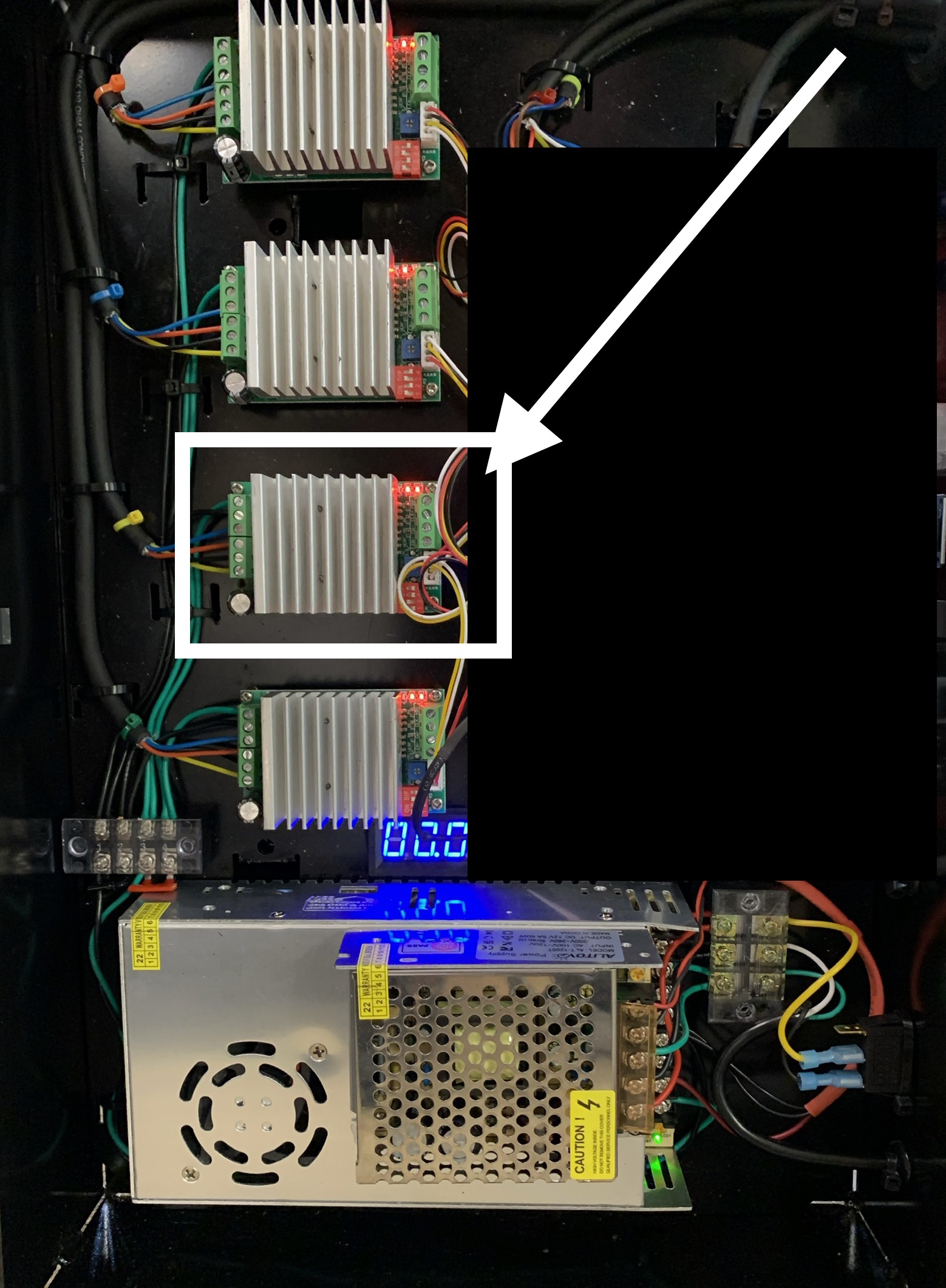
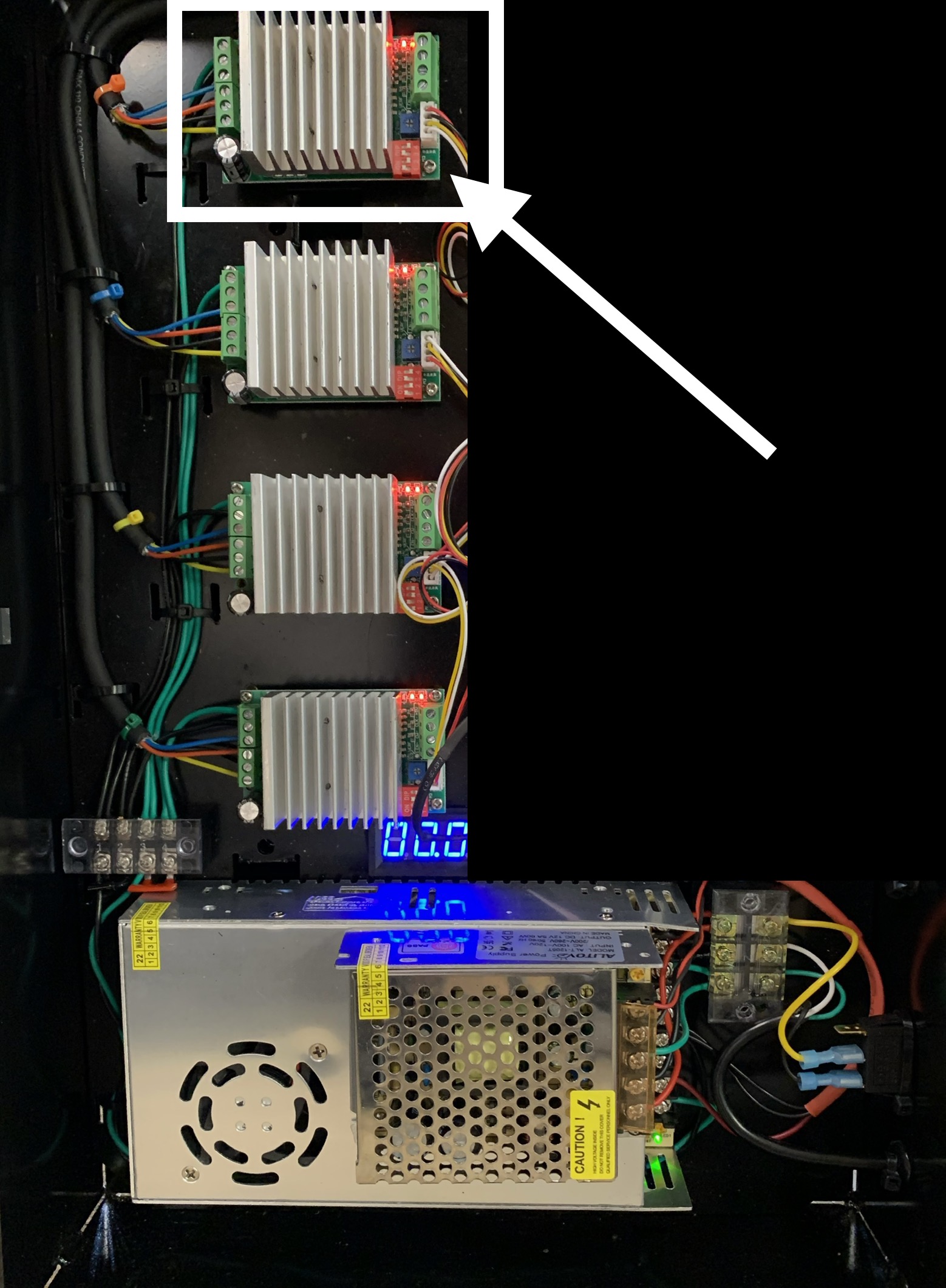
2. Locate the Z Driver (3rd from the Top)
3. Remove each Wire on the LEFT Side of the Driver and Place it back IN to the same loctation ensuring the Wire is Centered in the Opening and Tightened securely on the Bare Wire and NOT the Wire Coating.
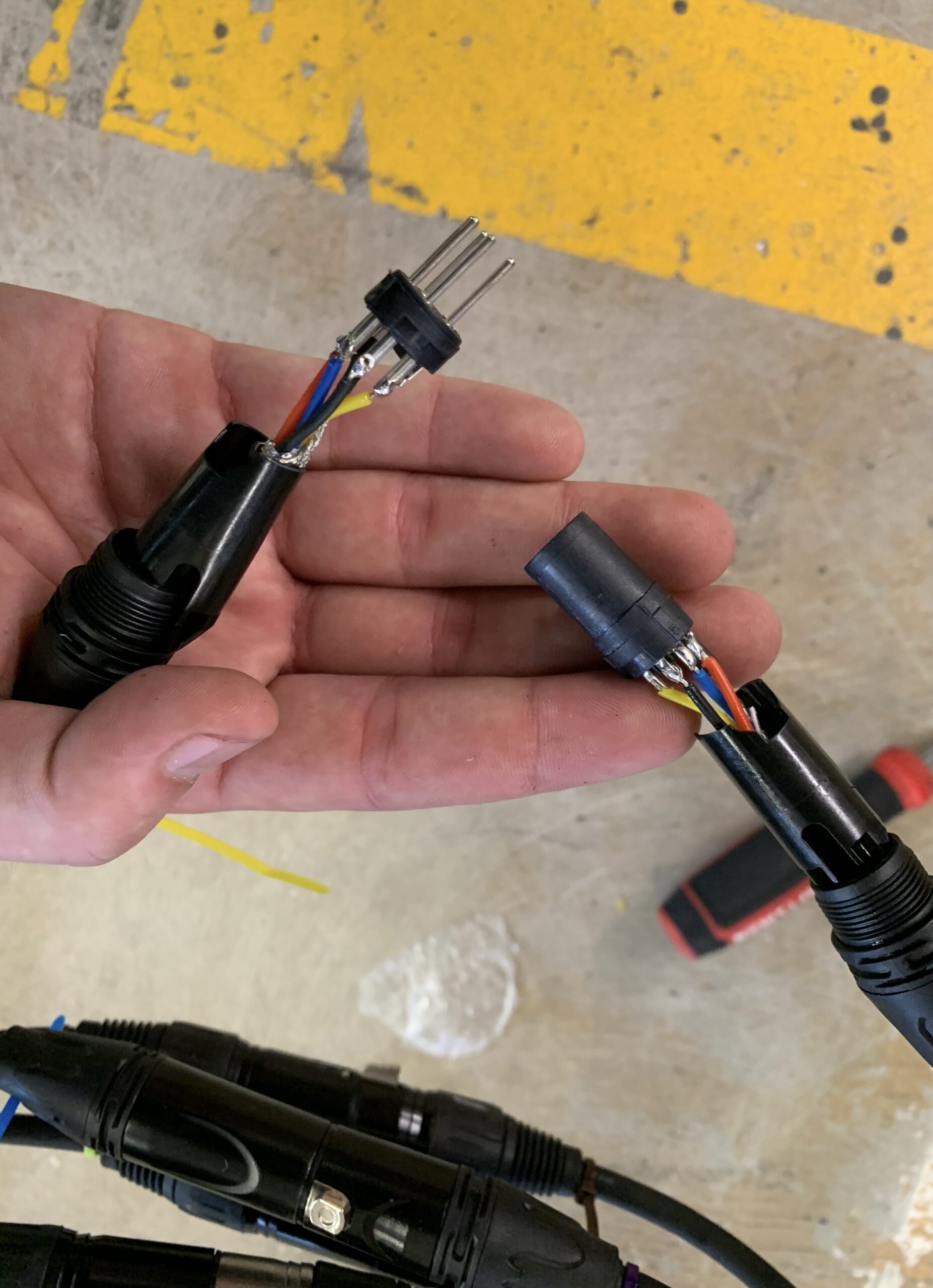
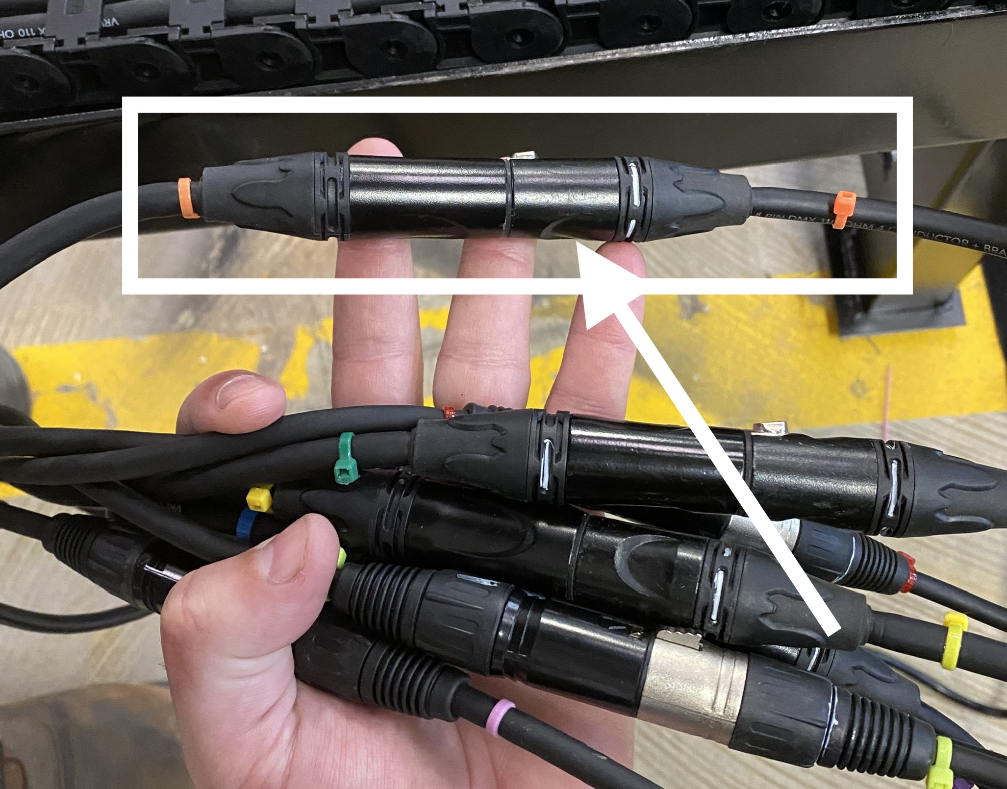
4. Locate the YELLOW Zip Tied Snap Connectors that Connect the Control Box to the Table
5. Disconnect the YELLOW Zip Tied Snap Connectors from each other
6. Unscrew the Covers to both YELLOW Zip Tied Snap Connectors
7. Verify there are No BURNED or MELTED areas on the Face of the FEMALE YELLOW Zip Tied Snap Connector.
8. Verify NO Pins are Pushed IN or receeded on the MALE YELLOW Zip Tied Snap Connector
9. Verify all 4 Wires are Soldered securely to the Pins
10. Verify NO Wire is Exposed to the extent that it could Touch any other Exposed Wire in the Connector or the Cover of the Connector (keep in mind the Wires may get twisted or bunched up when Screwing the Covers back ON)
11. Verify there are NO Loose Strands from any of the Wires that could Touch any other Exposed Wire in the Connector or the Cover of the Connector (keep in mind the Wires may get twisted or bunched up when Screwing the Covers back ON)
12. Remove the X Axis BACK Cover
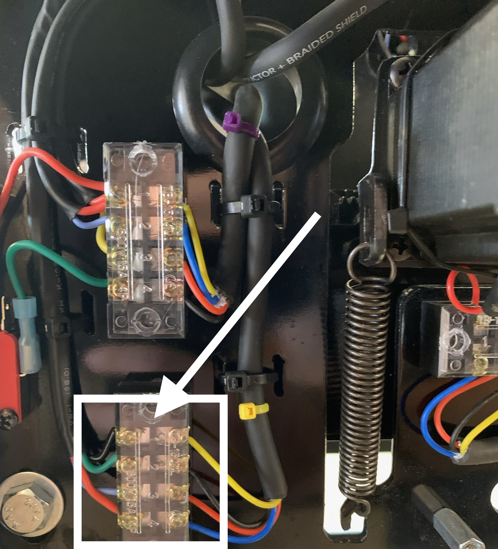
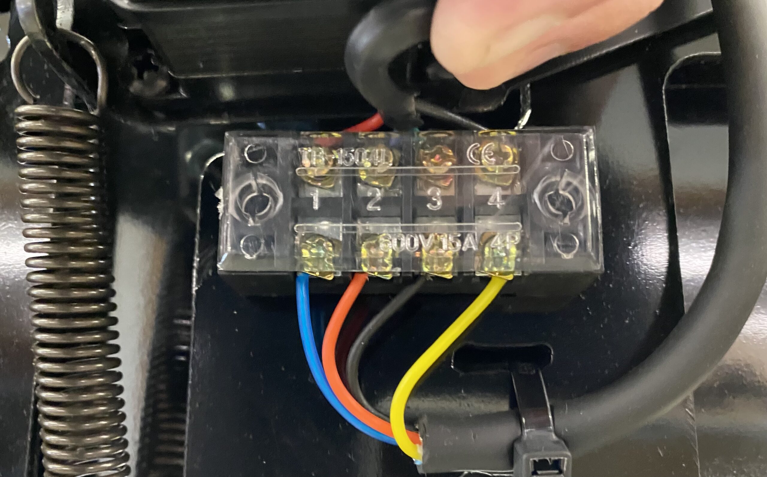
13. Locate the Screw Terinals on the LEFT Side of the X Axis (if you're staring at the Back of the X Axis - farthest Side away from the Control Box)
14. Locate the LEFT Side BOTTOM Screw Terminal for the Z Motor that has the same 4 Wires that are coming from the YELLOW Zip Tied Snap Connectors
15. Verify all 4 Wires on both Sides of the LEFT Side BOTTOM Screw Terinal are secure by Removing each Wire and Placing it back in its Place making sure you Tighten the Screws down on the Bare Wire and not the Wire Coating
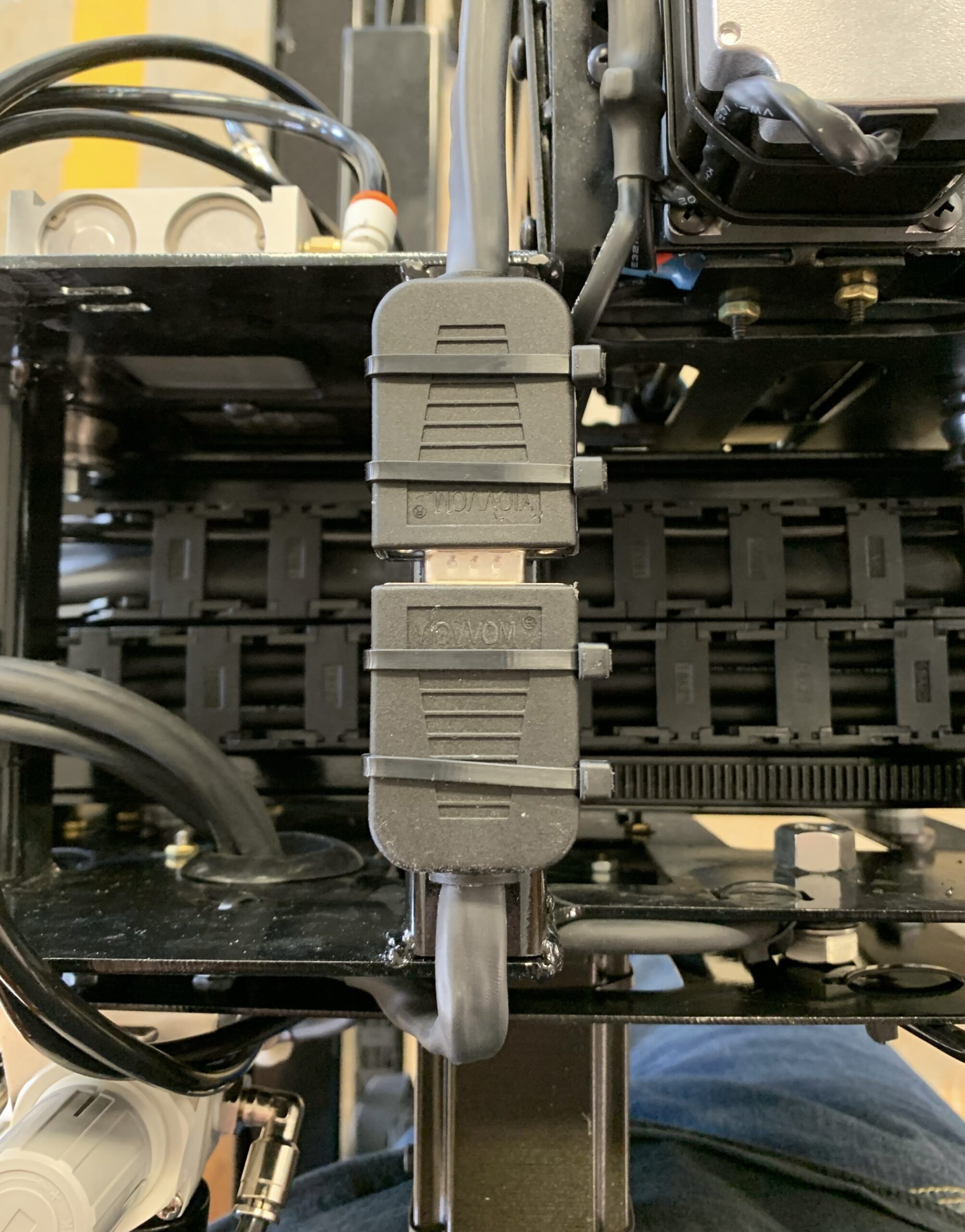
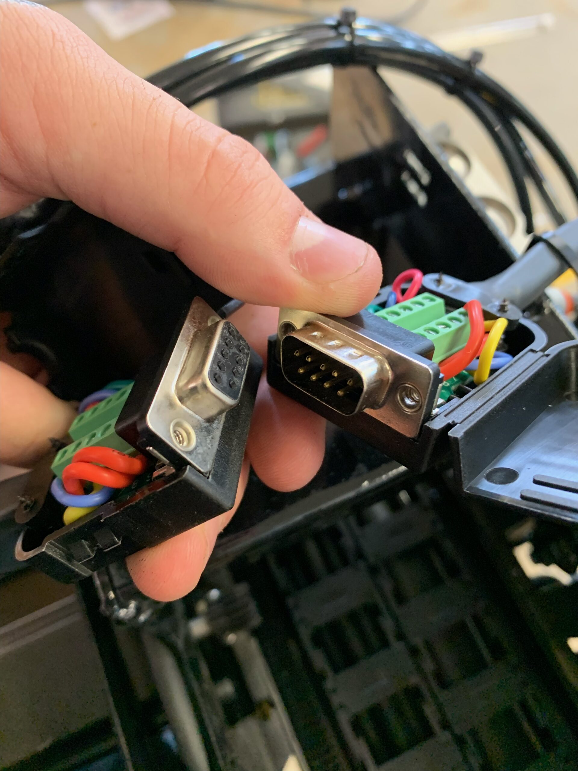
16. Disconnect the BLACK (DB9) Connectors on Top of the X Axis that Connect the X Axis and Z Axis to together
17. Check the Face of the FEMALE BLACK (DB9) Connector for any signs of Burning or Melting (if there are signs of Burning or Melting you'll need New BLACK (DB9) Connectors)
18. Check the Face of the MALE BLACK (DB9) Connector for any Pins that look Burned or Recessed (if there are signs of Burning or Melting you'll need New BLACK (DB9) Connectors)
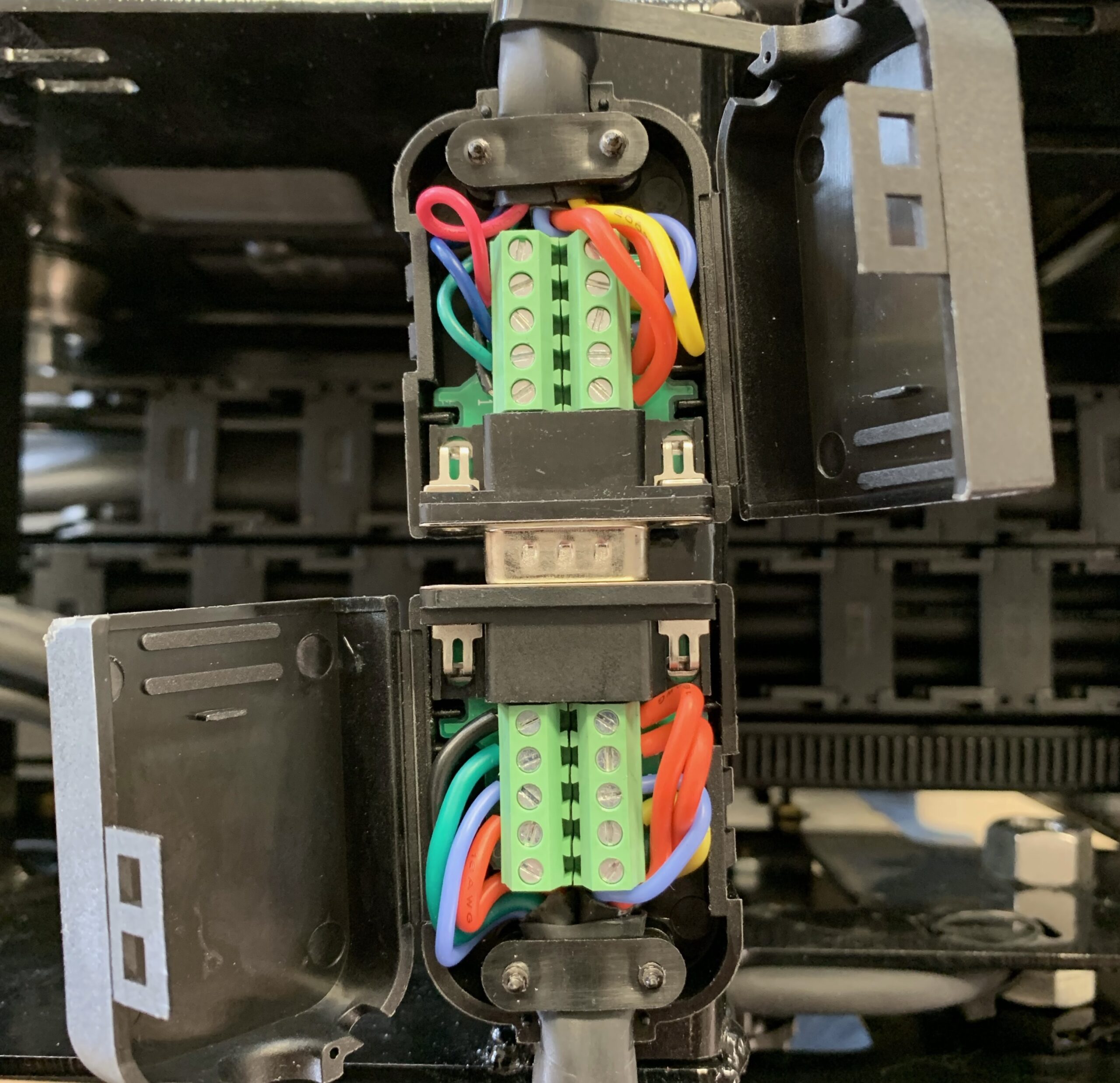
19. Open both BLACK (DB9) Connectors and Verify all Wires are secured by Removing each Wire and Placing it back in to the spot it was in and Tightening Down on the Bare Wire - NOT the Wire Coating
20. Make sure the BLACK (DB9) Connectors are Pushed IN to each other securely and not at an angle (if the BLACK (DB9) Connectors are NOT Pushed IN securely and Straight they will develop a Short and quit working)
21. Zip Tie the BLACK (DB9) Connectors securely to the X Axis
